Enclosure
A finger-jointed laser-cut acrylic box with a wet bay and a dry bay, plus the printed parts that live inside it.
Layout
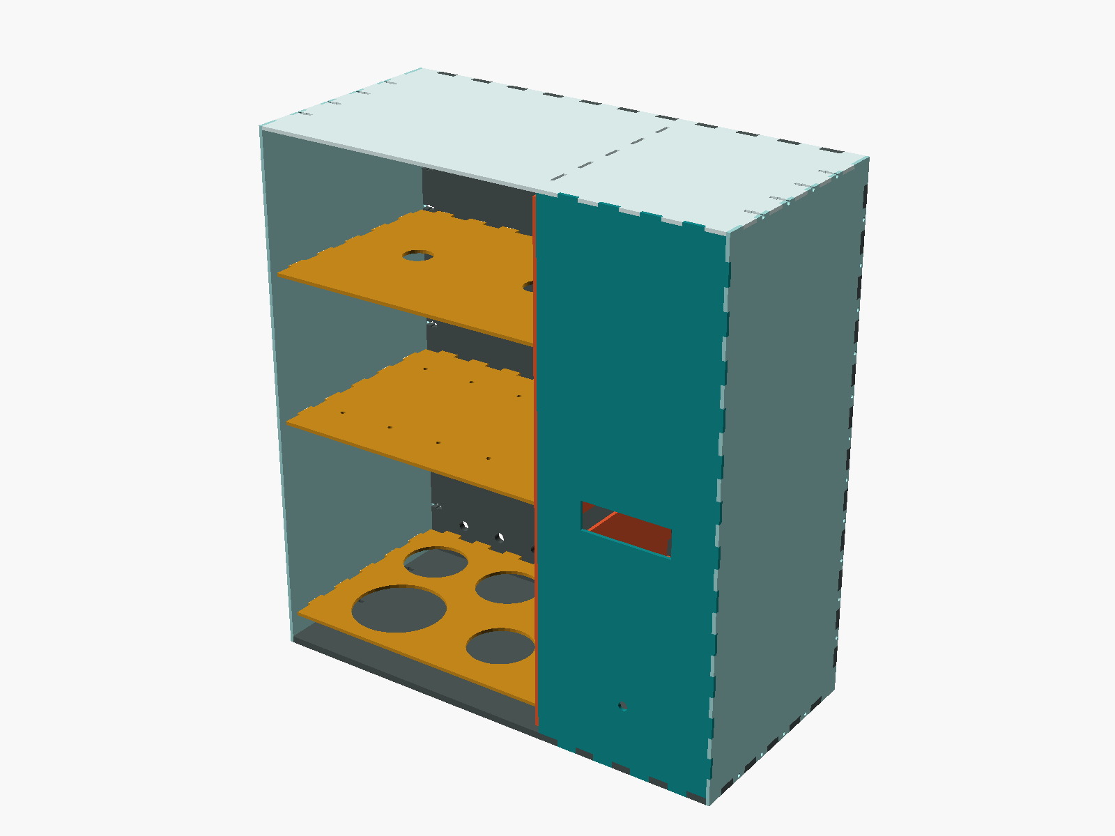
Outer size 420 W × 460 H × 200 D mm. A full-height bulkhead splits a 260 mm wet bay (left) from a 160 mm dry bay (right). Electronics never share air with liquids; cables pass through grommets in the bulkhead above the highest liquid level.
 front view                                 side view
 ┌──────────────────────────┬────────────┐  ┌──────────────┐
 │ cells shelf   z=330      │ Pi + carrier│  │  door  │     │
 │  [Cell A] [Cell B]       │ MCP · MOSFET│  │        │ dry │
 ├──────────────────────────┤ relay       │  │  wet   │     │
 │ syringe pump bank z=200  │             │  │  bay   │ bay │
 │  [SP1][SP2][SP3][SP4][SP5]│ PSU in      │  │        │     │
 ├──────────────────────────┤ fan         │  │drip tray│    │
 │ bottle tray   z=20       │             │  └──────────────┘
 │  ○ ○ ○ ○ ○ (acid)        │             │
 └──────────────────────────┴────────────┘
    waste bottle below, outside
Peristaltic pumps mount on the wet face of the bulkhead so tube runs to both cells are short. The drip tray covers the whole wet-bay floor with the leak sensor at its low corner.
Panels snap together
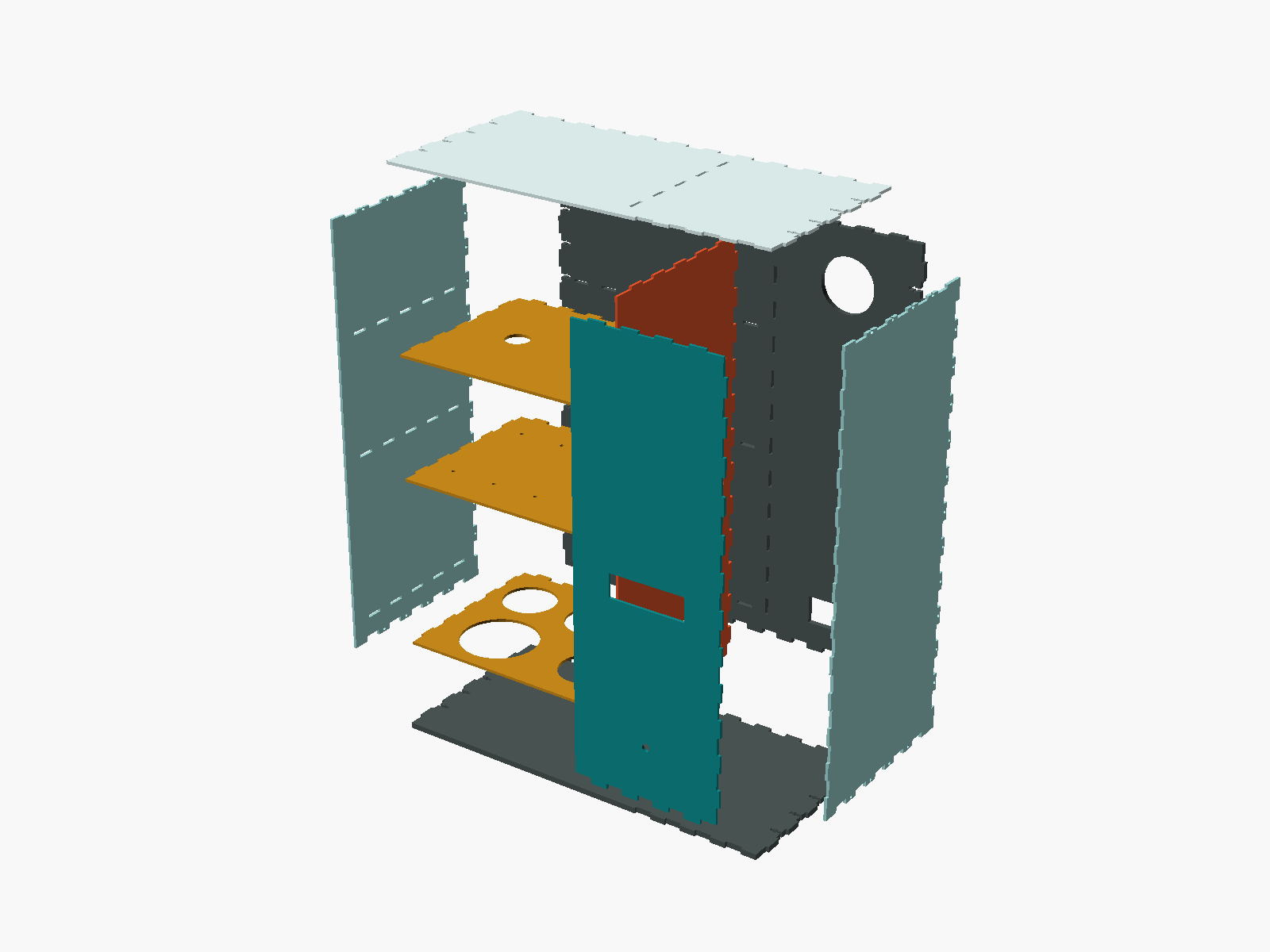
Every box edge is a finger joint: tabs on the base, back, top and dry-bay front panel land in notches on the two side panels; the back’s bottom and top edges tab into the base and top. The bulkhead and the three shelves tab through slots in the base, back, top and side, so they lock the box square. Tab depth always equals the mating panel’s thickness (3 or 6 mm), so joints finish flush.
The generator (hardware/analyzer/cad/panels.py) handles the fit:
| Parameter | Default | What it does |
|---|---|---|
--kerf |
0.18 mm | your laser’s kerf on 3 mm cast acrylic; measured on a test square |
--fit |
0.10 mm | interference after kerf: tabs are widened and slots narrowed by this, so panels press together and stay during assembly |
| T-slots | on | a bolt channel and captive-nut pocket in every other gap of the long joints, with matching holes in the sides: M3 × 12 bolts make the hold permanent |
Cut a 30 mm test joint first and adjust --kerf until a tab needs a firm thumb push. Cast acrylic is brittle: keep --fit at or below 0.10 mm and rely on the T-slot bolts (or a bead of Weld-On 4 on the inside) rather than a tighter press fit, which cracks over months.
cd hardware/analyzer/cad
python panels.py --kerf 0.18 --fit 0.10 --out panels.svg      # cut file
python assembly.py && openscad -o enclosure_assembly.stl enclosure_assembly.scad   # 3D check / viewer
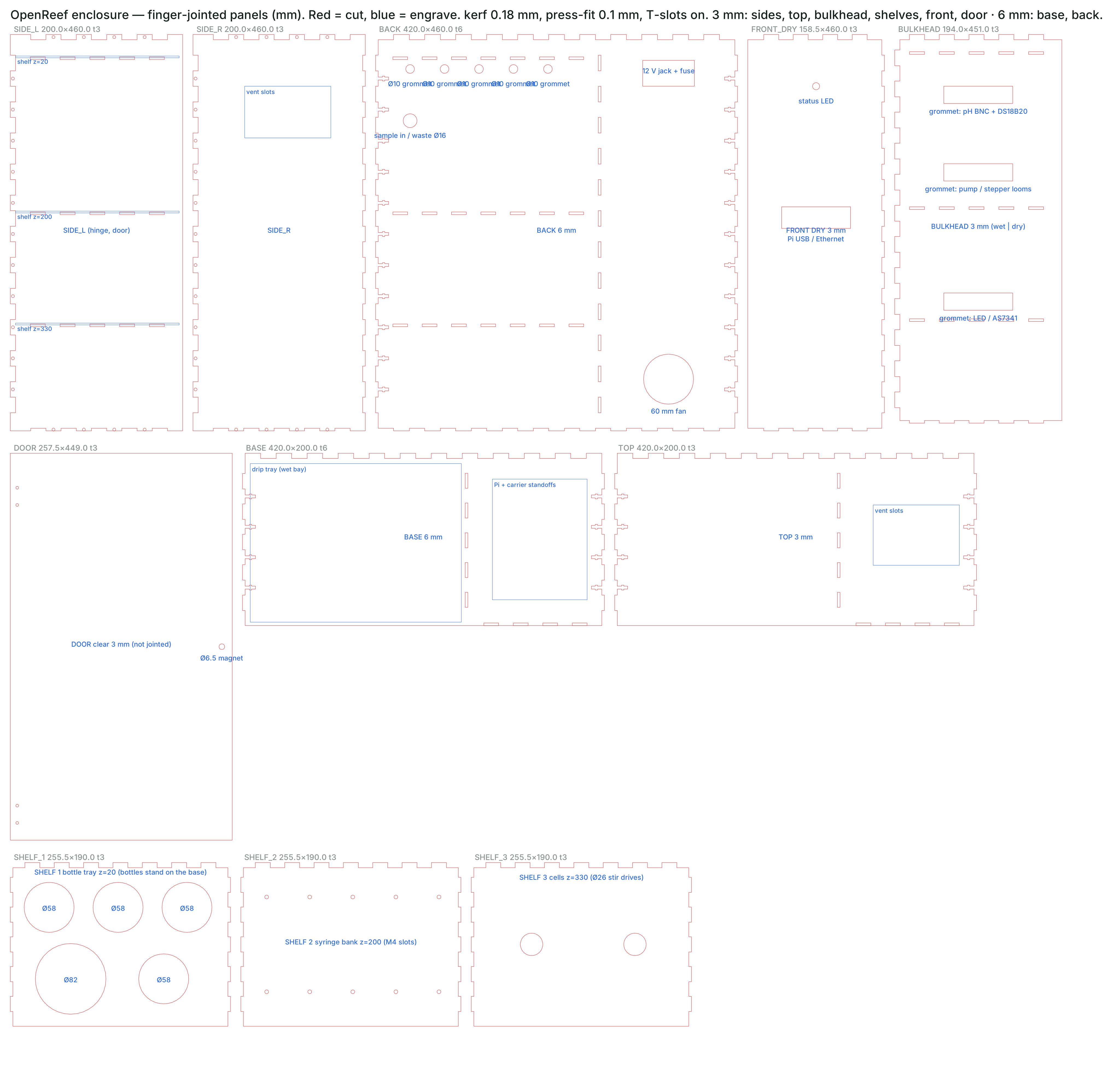
panels.svg is the cut file: red = cut, blue = engrave, 1 user unit = 1 mm (import at 100 % scale). Base and back are 6 mm; everything else 3 mm. The door is clear acrylic on two hinges with a magnet catch and is the only panel that is not jointed. The 16 printed corner brackets (corner_bracket.scad) are now optional — use them only if you cut the panels without T-slots.
Note on handedness: the panels are symmetric, so the same cut file builds the box with the wet bay on either side. Install the shelf-slotted side (SIDE_L) on the side you want the wet bay, with the engraved marks facing inward.
Printed parts
| Part | File | Qty | Material | Notes |
|---|---|---|---|---|
| Syringe pump frame, carriage, plunger clip | syringe_pump.scad |
5 sets | PETG | 4 walls, 30 % infill |
| Cell A cap | cell_a_cap.scad |
1 | PETG | 100 % infill plug; 38 × 2 mm O-ring |
| Cell B holder body | cell_b_holder.scad (part=”body”) |
1 | black PETG | 100 % infill walls for light-tightness |
| Cell B lid | cell_b_holder.scad (part=”lid”) |
1 | PETG | |
| Corner bracket (optional) | corner_bracket.scad |
0–16 | PETG | only without T-slots |
| Stir drive mount | included in cell holder shelf cut-out | 2 | — | 40 mm fan + 2 magnets |
Set part at the top of each SCAD file to export individual STLs. The OpenSCAD files are parametric: syringe diameter, stroke, lead-screw pitch, cuvette diameter and tube diameters are variables at the top.
Renders
 |
 |
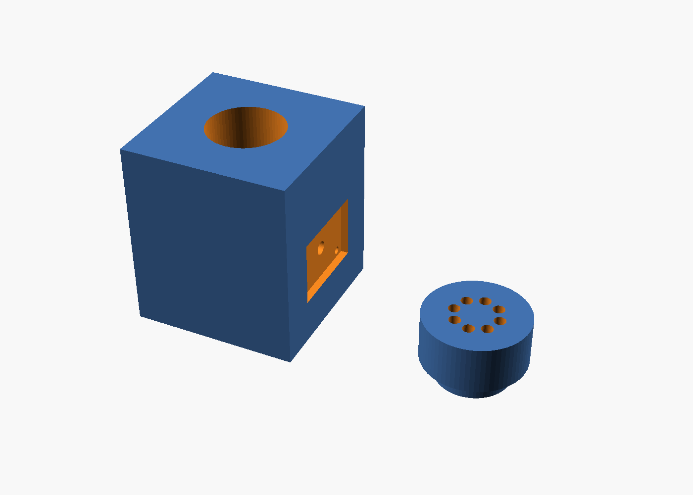 |
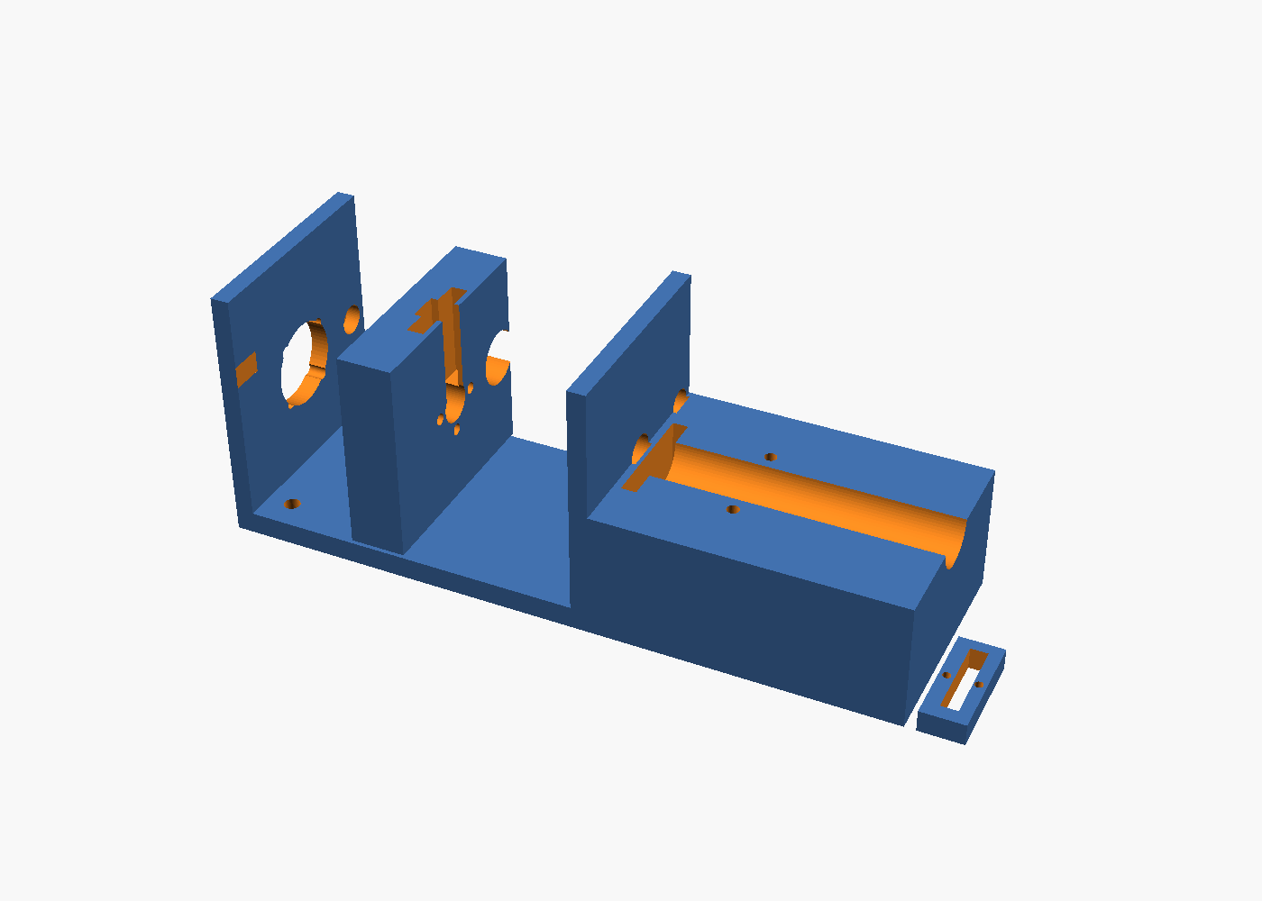
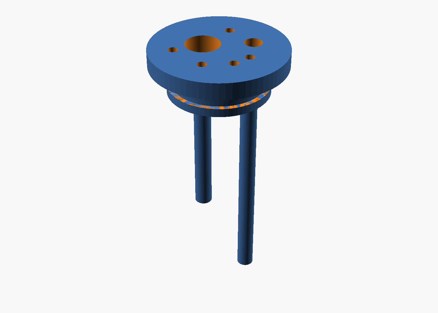
| Syringe pump: frame, carriage, plunger clip | Cell A cap with level and drain tube guides | Cell B light-tight holder and 8-port lid |
All renders are produced from the SCAD sources with openscad -o renders/<part>.png --autocenter --viewall <part>.scad.
Assembly notes
- Dry-fit the box without the T-slot nuts first: base → back → bulkhead → shelves → sides → top → dry front. Tap tabs home with a rubber mallet through a wood block.
- Mount the bottle tray 20 mm above the base so spilled reagent runs into the drip tray, not under the tray.
- Route all tubing so that free ends are above liquid levels — no siphons.
- Put the 60 mm fan in the dry bay back panel blowing out; intake slots in the right side panel. The TMC2209 drivers barely warm up, but the PSU brick should stay outside.
- Label every tube at both ends before you close the door. Future you will thank you.