Fluidics
Two cells, five syringe pumps, six peristaltic pumps and how liquid moves between them.
Flow diagram
 tank/sump ──100 µm filter──┬── FILL_A ──▶ ┌─────────────┐
                            │              │   CELL A    │ pH electrode · DS18B20 · stir bar
                            │  LEVEL_A ◀── │  20.0 mL    │ ◀── SP1  0.02 N HCl (drip tip)
                            │  DRAIN_A ◀── └─────────────┘
                            │
                            └── FILL_B ──▶ ┌─────────────┐
                               LEVEL_B ◀── │   CELL B    │ AS7341 · white + 850 nm LEDs · stir bar
                               DRAIN_B ◀── │  10.0 mL    │ ◀── SP2 NP R1   ◀── SP3 NP R2
                                           └─────────────┘ ◀── SP4 NP R3a  ◀── SP5 NP R3b
   LEVEL_* and DRAIN_* ──────────────────────────▶ 2 L HDPE waste (float switch)
Cells
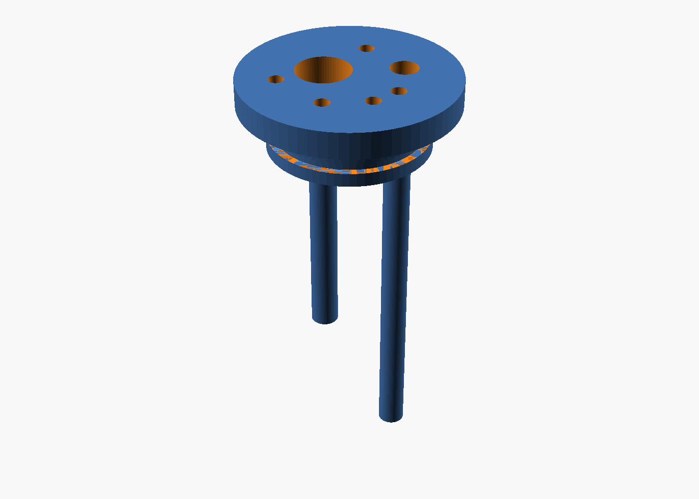 |
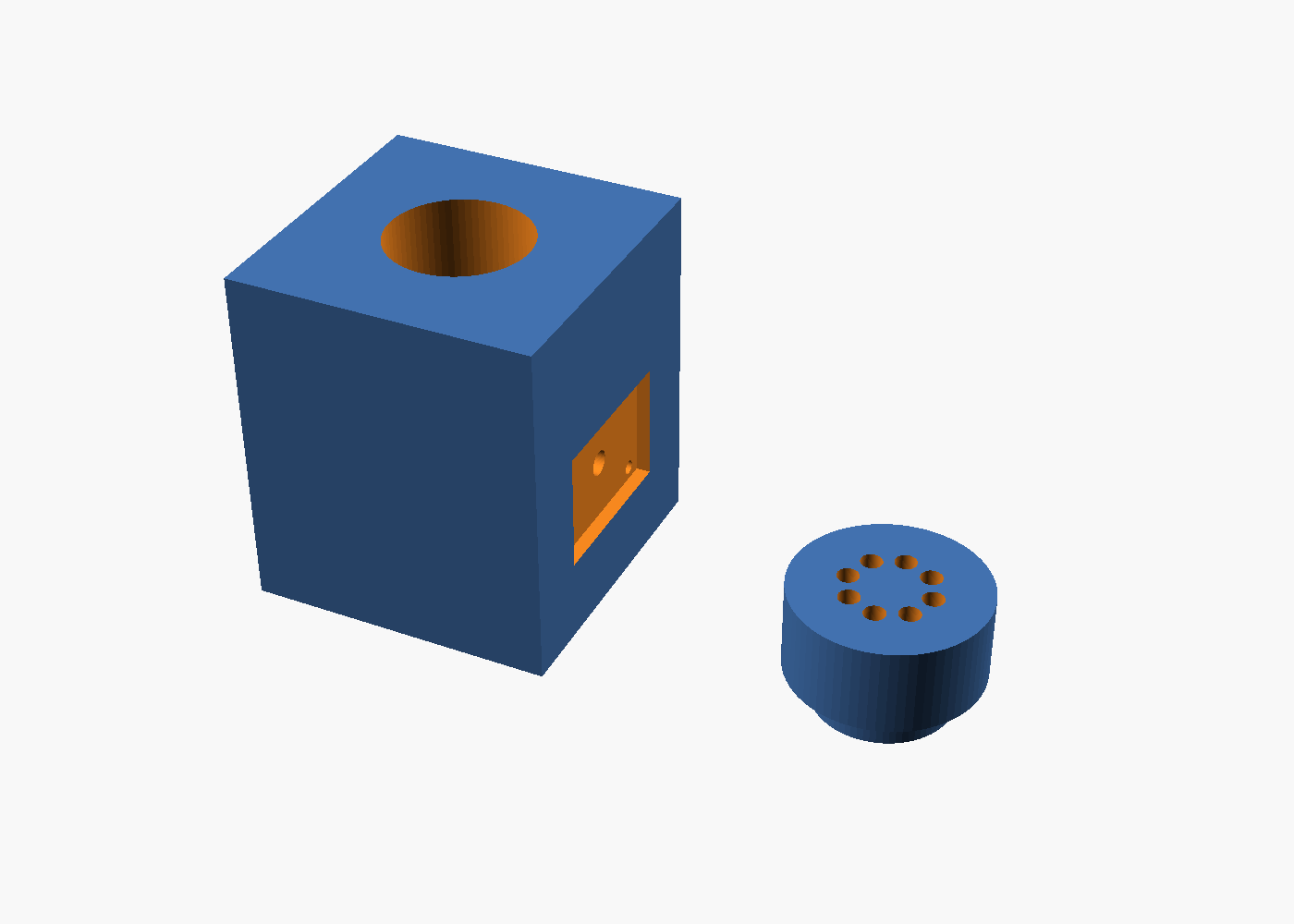 |
|---|---|
| Cell A cap: electrode, probe, fill/level/drain tubes, acid tip, vent | Cell B holder body (sensor pocket side) and 8-port lid |
Cell A is a 60 mL borosilicate vial (40 × 100 mm). A printed cap (cell_a_cap.scad) carries the 12 mm pH electrode, the DS18B20, the fill tube, the level dip tube whose tip sets 20.0 mL, the drain dip tube reaching the bottom, the acid drip tip (above the liquid, so acid never back-diffuses into the syringe line) and a vent. A 25 mm PTFE stir bar is driven by a 40 mm fan with two magnets glued to the hub, mounted under the shelf.
Cell B is a 22 mm round glass cuvette (Hanna HI731331 type) in a black PETG holder (cell_b_holder.scad). The AS7341 sits behind a 4 mm aperture on one face; the white and IR LEDs sit on the opposite face 8 mm apart, both aimed at the bore centre 22 mm above the bottom, above the 8 mm stir bar. The lid has eight 3.4 mm ports: fill, level, drain, four reagent tips, vent.
Volume metering
Fill pumps overfill the cell by 30 %; after a 2 s settle, the level pump runs long enough to remove 60 % of the nominal volume — more than the excess — so it draws air for the last few seconds and the liquid surface ends exactly at the tube tip. Repeatability is about ±1 % (surface tension and tube-tip geometry); the calibration against a reference standard absorbs the systematic part. Trim the tubes once with a scale: 20.0 g and 10.0 g of water.
Syringe pumps
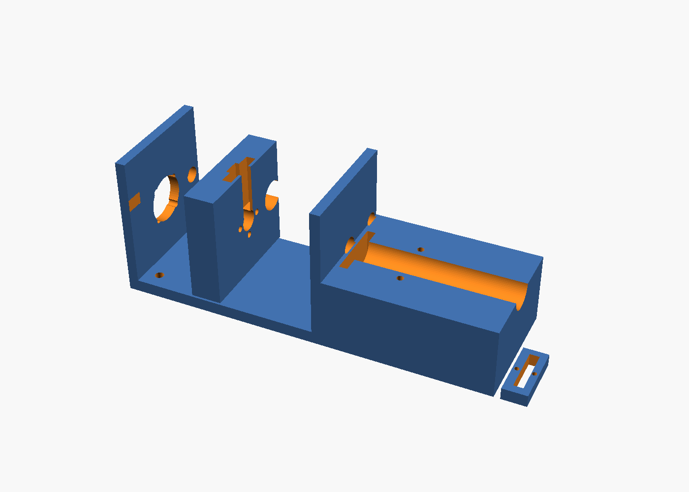
Each pump is a NEMA17 (17HS4023), a T8×2 lead screw with brass nut, an 8 mm guide rod with LM8UU, a 5 mL glass luer-lock syringe and two luer check valves. The carriage captures the plunger thumb rest so the motor can both push and pull. At 1/16 microstepping:
Dispensing: the software pushes the commanded volume; when the syringe is nearly empty it retracts to the home switch (aspirating from the bottle through the inlet check valve), pauses 0.5 s for the valve to seat, and continues. Homing happens only while the cell is empty because the 0.5 mm back-off stroke expels about 60 µL through the outlet.
Why not peristaltic for reagents: tube wear changes the volume per revolution by several percent within weeks, and reagent dose errors translate directly into concentration errors. Syringe pumps with check valves are the same mechanism commercial analyzers use.
Peristaltic pumps
Six 12 V peristaltic pumps (Kamoer KPHM100 class, 1–1.5 mL/s) run open-loop by time. They only move sample and waste, so their accuracy does not matter beyond “overfill by about 30 %”. Replace the silicone tube segments every 6 months. Set each pump’s measured ml_per_s in config.yaml (time a 60 s run into a measuring cylinder).
Tubing and materials
| Line | Material | Why |
|---|---|---|
| Acid and NP reagents | PTFE 1/16” ID | chemical resistance, no permeation |
| Sample, rinse, waste | Silicone 2 × 4 mm | flexible, cheap, fine for seawater |
| Pump segments | Platinum-cured silicone | longest peristaltic life |
| Check valves, fittings | PP / silicone | acid tolerant |
| Caps, holders | PETG | acid and salt tolerant, printable |
| Cells | Borosilicate glass | optical quality, inert |
Rinse strategy
Before every test the target cell is filled and drained twice with tank water (also flushing the stale sample line). After a colorimetric test the cell is rinsed twice more so reagent residue cannot reach the next blank. Cells are parked full of tank water between tests to keep the electrode wet and the cuvette from drying with salt rings.
Maintenance intervals
| Item | Interval |
|---|---|
| Peristaltic tube segments | 6 months |
| Check valves | 12 months, or when a prime shows air |
| pH electrode | 12–18 months (check slope at calibration) |
| Cuvette | wipe at reagent change; replace if scratched |
| Stir bars | inspect yearly |
| Intake filter | rinse monthly |